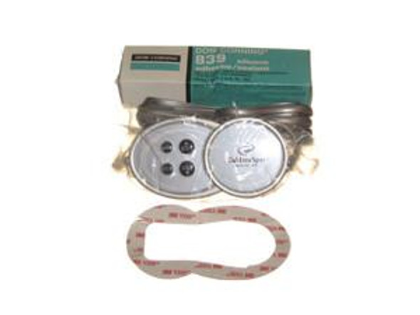
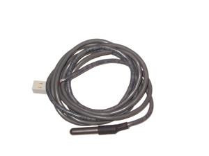
2004 Caldera Spas Aspire Topside Control Panel, 73188
- SKU:
- 73188
Description
2004 Caldera Spas Aspire Topside Control Panel 2 Pump Elation - Aspire (No Air Control) The control panel uses a main display to show the status of the Spa Control System and other LED messages. The main display shows which spa functions are active (light, jets, summer timer, locking features).The control head, located on the bar top, consists of an electronic board and housing with a conformal-coated moisture, resistant barrier. The control head serves as an interface between the control panel and the control box. The control head has the control thermostat, light dimmer, diagnostic LEDs and jet switches incorporated into it. When the control panel is used to activate one of these functions, the control head registers the command and sends a signal to the control box, telling it to activate the chosen function. CONTROL BOX REMOVAL AND INSTALLATION: Removing the Control Panel 1. Turn the power off to the spa. 2. Remove the equipment compartment door. 3. Access the control box. 4. Disconnect the control panels modular connector/ribbon cable in the control box. On the bartop: 4. Make sure the water line is at least six inches, the bottom of the control panel. 5. Using a thin metal blade, i.e. a putty knife, gently pry around the edges of the panel. 6. Remove the panel, gasket material, silicone, and cable from the opening in the shell. Installing the New Control Panel 1. Align the panel with the opening and thread the ribbon cable through the opening in the shell and down to the control box. 2. Rest the control panel in the location where it will be installed. 3. Connect the cable into the appropriate receptacle on the circuit board; refer to the Electrical Schematic. 4. Apply power and verify that the following functions are operative. Run all functions to be sure the control panel is fully operative. Indicator Lights Locking Features Jets Light Set Temperature 4. Locate the gasket in the kit. 5. Disconnect the panel and dry fit the gasket. Masking tape can be used to outline proper placement. 6. Remove the remaining backing from the gasket, and adhere the gasket to the bartop. 7. Place a 1/8 bead of clear silicone to the lip area of the control panel. 8. Fit the panel onto the gasket and press down evenly to secure it in place. 9. Use the clean towel or rag to remove any excess silicone from the area. 10. Inform the spa owner to wait 24 hours before using the spa to allow the silicone to dry completely. 2008 Watkins Manufacturing Corporation. CDR is a trademark of Watkins Manufacturing Corporation
View AllClose


